-1.png "Starter - Blogger Template")
Gd&T Pattern Of Holes
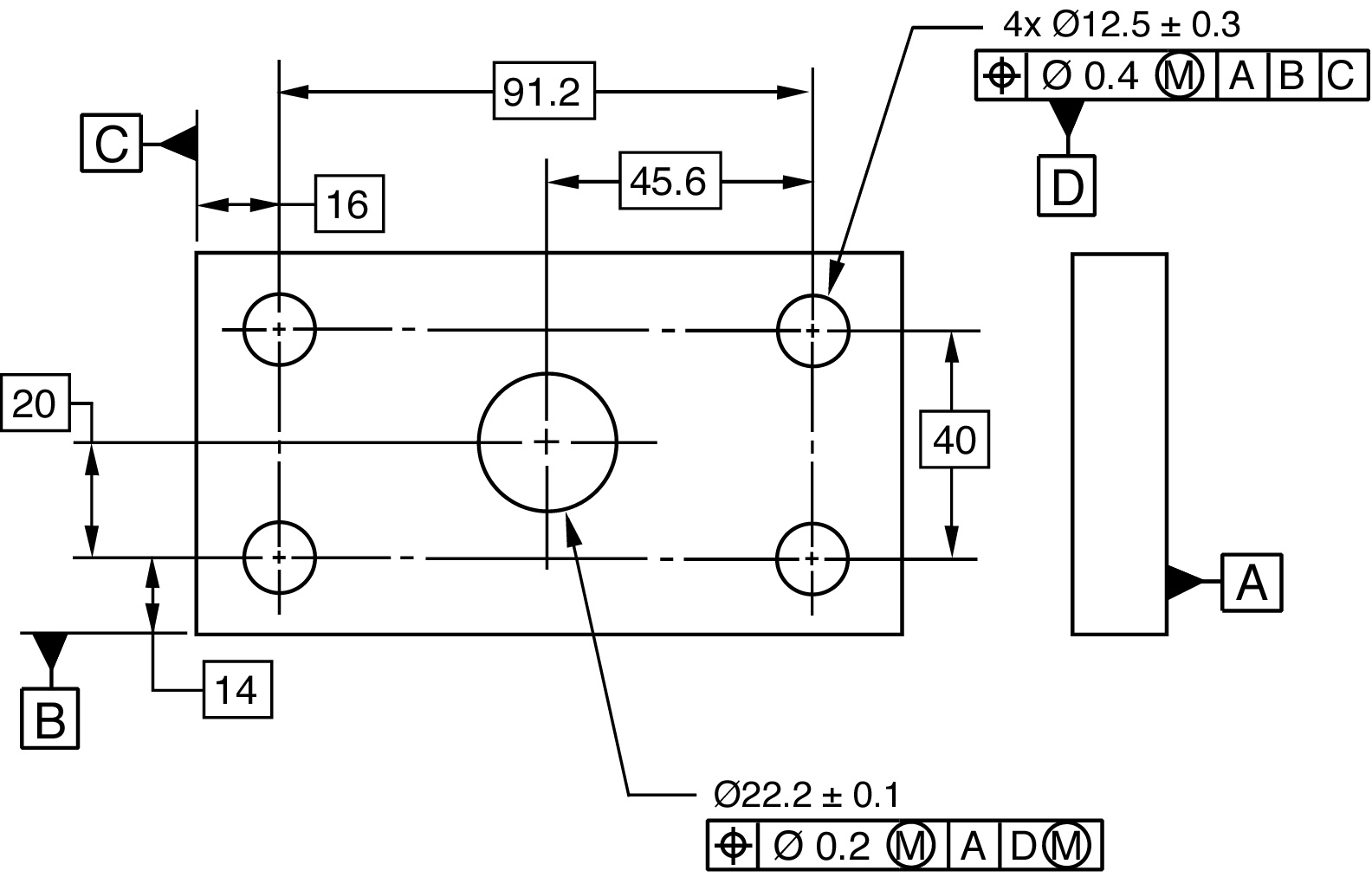
Gd&T Pattern Of Holes - Do you want to reduce production costs? The large center hole is then located to [a] primary, and [b] secondary. Web the holes are located by basic dimensions from the datum edges. Why should i use gd&t to detail simple parts? Web quickly shows how to use gd&t to locate a circular pattern of clearance holes on a flat plate. Web gd&t is a particular set of conventions used on engineering drawings (often called “prints” from the older “blueprints”) that communicate how parts should fit together and how they function.
Web a simple example would be a set of holes (pattern) used to affix a name plate. The tolerance indicated by the upper control frame is. Web quickly shows how to use gd&t to locate a simple clearance hole on a flat plate.instagram: The position of these holes is defined using basic dimensions with respect to the datum reference frame abc. The large hole in the middle of the part is then.
Are You Using GD&T Correctly? Geometric Learning Systems
In this case, the two hole patterns are clocked together as multiple patterns of features, explained above, however they are free to rotate about the axis of datum feature b. Do you want to map complex relationships in one part? The relative position of the holes is important (tighter tolerance), in order to match the same hole on the plate.
GD&T Blog Geometric Learning Systems

Web the holes are located by basic dimensions from the datum edges. The tolerance indicated by the upper control frame is. The relative position of the holes is important (tighter tolerance), in order to match the same hole on the plate itself, but the absolute position of the entire pattern on the part may be less critical (looser tolerances) as.
Position tolerance of circular pattern some questions Drafting

Web hole pattern located by composite tolerancing (primary and secondary datums in lower segment). The large hole in the middle of the part is then. Do you want to reduce production costs? For starters, there are three categories of geometric tolerances: An example of this is shown below in figure 1, where we have a drawing of a.
Composite Position Tolerance for Hole pattern. Drafting Standards, GD

Web gd&t is a particular set of conventions used on engineering drawings (often called “prints” from the older “blueprints”) that communicate how parts should fit together and how they function. This figure represents one of the possible displacements of the pattern. Web this guide explains gd&t symbols, principles of dimensioning and tolerancing, and provides guidelines for both traditional and digital.
GD&T Tip Datums Watch placement of datum triangles in the latest

Web however, the basic concepts identified below provide a solid introduction to the topic, highlighting ways in which gd&t can be used to control fits of holes/shafts in order to provide additional control on the fit geometry. A datum feature is the tangible surface or feature of size (comprised of multiple surfaces or revolved surfaces) that is indicated by the.
Gd&T Pattern Of Holes - When installing repeated elements such as a perforated hole pattern, first position the pattern and then specify interrelated distances rather than referencing elements to a fixed edge or. In this case, the two hole patterns are clocked together as multiple patterns of features, explained above, however they are free to rotate about the axis of datum feature b. The tolerance of position locates the holes within the pattern relative to each other. All four locating holes are designated as pattern datum [b]. For starters, there are three categories of geometric tolerances: Web hole pattern as a datum feature upcoming of gd&t/gps (english) online training will open on april 10 new gd&tip :
In this case, the two hole patterns are clocked together as multiple patterns of features, explained above, however they are free to rotate about the axis of datum feature b. Do you want to map complex relationships in one part? Datums are theoretically exact points, axes, lines, and planes or a combination thereof that are derived from datum features. Web we often see a pattern of holes as an assembly feature on a part. We can visualize each hole’s tolerance zone as a cylinder with a diameter of ø.016 inches, having an axis perfectly perpendicular to.
Web We Often See A Pattern Of Holes As An Assembly Feature On A Part.
In the illustration below, the mmc of the hole is 19.5mm and the lmc of the hole is 20.5mm. Do you want to reduce production costs? Everything is called out mmc and mmb because our only concern is assembly. The relative position of the holes is important (tighter tolerance), in order to match the same hole on the plate itself, but the absolute position of the entire pattern on the part may be less critical (looser tolerances) as long as the orientation is good.
Web When You Have A Hole In A Part Such As A Bolt Pattern, True Position Is Usually Called Out.
Web gd&t is a particular set of conventions used on engineering drawings (often called “prints” from the older “blueprints”) that communicate how parts should fit together and how they function. The tolerance of position locates the holes within the pattern relative to each other. / discord this video was created to help. Web quickly shows how to use gd&t to locate a circular pattern of clearance holes on a flat plate.
Web On The Right, The Pattern Of Four Holes Is A Primary Datum.
Web the holes are located by basic dimensions from the datum edges. The large center hole is then located to [a] primary, and [b] secondary. When a part is bolted down, the pattern of holes sets the location of that part. Web quickly shows how to use gd&t to locate a simple clearance hole on a flat plate.instagram:
It Is Shown To Be A Composite Tolerance Because There Is One Geometric Symbol That Spans Across The Two Frameworks.
An example of this is shown below in figure 1, where we have a drawing of a. Figure 1 shows a composite fcf controlling position tolerance of a pattern of holes. We are now making this available to everyone in a four part series! When installing repeated elements such as a perforated hole pattern, first position the pattern and then specify interrelated distances rather than referencing elements to a fixed edge or.